Basement and semi-basement facilities serve different purposes. Previously, vegetable stores were arranged in them, communications were located. Now cellars are assigned other functions, from garages to gyms and even offices.
In any case, forced ventilation in the cellar of the building is a justified need, dictated by the need for a planned supply of fresh air to replace the exhaust. We offer a good understanding of this issue.
Each cellar has its own ventilation
An in-depth vegetable storehouse located under a private house is forced, i.e. mechanical ventilation is not needed.
Fruits and vegetables are stored better if air exchange in the basement is minimal. Therefore, the simplest products and supply and exhaust ventilation ducts will be enough.

Vegetables stored in the cellar during the winter cannot be ventilated intensively. They just freeze - frost on the street
According to design standards for vegetable stores NTP APK 1.10.12.001-02ventilation, for example, potatoes and root crops should occur in a volume of 50-70 m3/ h per ton of vegetables. Moreover, in the winter months, the ventilation intensity should be halved so as not to freeze the root crops.
Those. in the cold season, ventilation of the cellar should be in the format of 0.3-0.5 air volume per hour.
The need for forced ventilation in the cellar arises if the scheme with the natural movement of air flows does not work. However, the elimination of sources of waterlogging will also be required.
Image Gallery
Photo from
Forced ventilation fan
Removing excess moisture from the cellar
Supply opening in the basement of the house
Storage conditions
Moisture in the basement
Mustiness and humidity are common problems in basements. The first problem is due to insufficient air exchange. The basement is buried 2.5-2.8 m into the ground, its walls are made with maximum moisture and air impermeability.
And the natural ventilation, represented by vertical house channels, is absent in many basements and cellars.

Before analyzing the ventilation of the cellar, its walls should be waterproofed. Basement ventilation will not solve the problem of wall hygroscopicity
Significant air humidity in the basement is caused by poor waterproofing of the walls. The second reason is worn pipelines running through the basement utility rooms. Moreover, condensate is deposited on them, regardless of the integrity of the pipes and the tightness of detachable joints.
The problem of excess humidity must be solved before the development of the project and the construction of the ventilation system of the basement. It is necessary to restore or increase the degree of tightness of the walls of the cellar, to seal the pipelines and close them with insulation.
The latter measure will eliminate the effect of condensate on the pipe material. Then the ventilation needs of the cellar are determined.
Image Gallery
Photo from
Duct ventilation system
Installing a fan in the center of the duct
Combined ventilation variant
Forced ventilation fan
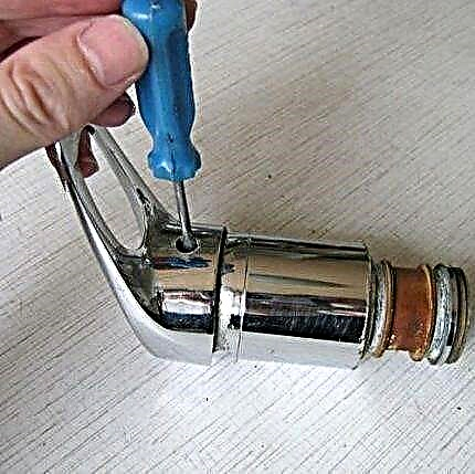
Thermal insulation of pipes from condensate
Drops of water arise only on the surface of household pipelines through which cold liquid flows (drinking water and sewage). The moisture in the atmosphere of the rooms condenses on the cold pipes due to the temperature difference between their surface and the air.
The colder the pipe, the more air saturated with moisture - the more actively the process of condensation of water occurs.

If cold water flows through the pipe, condensation will collect on it. Each such pipe must be covered with thermal insulation.
The difference in air temperature and the surface of the cold water pipes in private homes is usually small. Indeed, with infrequent consumption of cold water by households, there is no movement of it through the pipes, so the temperatures of the home atmosphere and the pipeline are almost equal.
But in a multi-story building, residential or office, cold water is used almost continuously and the pipe is constantly cold.
The easiest way to deal with condensate on pipes is to equalize the temperatures of the pipes and the atmosphere. It is necessary to close the cold pipeline with steam and heat insulating material along the entire length.
Condensate collects on a cold pipe, regardless of what it is made of. Polymers, ferrous metals, cast iron or copper - it does not matter. It is necessary to isolate all pipes of "cold" communications!

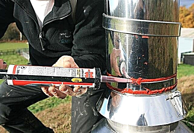
It is not difficult to isolate water pipes from the effects of condensate and wet suspension in the air. All you need is a tube made of foamed LDPE, a wallpaper knife and reinforced tape
To prevent contact of a cold pipe with air, a tubular heat insulator made of foamed LDPE will allow. The wall of the heat-insulating “tube” is at least 30 mm. The diameter of the tubular insulation is chosen slightly larger than that of a pipeline insulated from atmospheric humidity. It is simple to put on a heater - cut along the length, then tighten the pipe with it.
Immediately after sealing the pipeline with a heat insulator, it is necessary to wrap it on top with reinforced adhesive tape for pipes. For maximum thermal insulation and greater attractiveness, wrapping with foil tape (aluminum) is carried out.
Shutoff valves and difficult-curved sections of the cold pipeline, which cannot be closed by tubular insulation, are wrapped with adhesive tape in several layers.
Calculation of air exchange in the basement
Before you search for ventilation equipment and plan the location of ventilation ducts in the basement, you need to determine the need for air exchange. In a simplified format, i.e. excluding the possible content of harmful substances in the atmosphere of the basement, the air exchange in it is calculated by the formula:
L = Vunder • KR
Wherein:
- L - estimated need for air exchange, m3/ h;
- Vunder - basement volume, m3;
- KR - minimum air exchange rate, 1 / h (see below).
The obtained air exchange value will allow to establish the power characteristics of the forced ventilation system of the basement.

The calculation of the air volume of the basement is made by multiplying the height, width and length
However, to calculate the formula, data on the air volume of the room and the air exchange rate are required.
The first parameter is calculated as follows:
Vunder= A • B • H
Where:
- A is the length of the basement;
- B - basement width;
- H - basement height.
To determine the volume of a room in cubic meters, the results of measurements of its width, length and height are translated into meters. For example, for a basement 5 m wide, 20 m long and 2.7 m high, the volume will be 5 • 20 • 2.7 = 270 m3.

The need for air exchange in this room directly depends on the number of people in it. The degree of physical activity of visitors is also taken into account.
For spacious basements, the minimum air exchange ratio KR determined from the calculation of the needs of one person in fresh (supply) air per hour. The table shows the normative human needs for air exchange, depending on the use of this room.
Also, air exchange can be calculated by the number of people who will be (for example, working) in the basement:
L = Lpeople• Nl
Where:
- Lpeople - norm for air exchange for one person, m3/ h • people;
- Nl - estimated number of people in the basement.
The norms approve human needs in 20-25 m3/ h of supply air with weak physical activity, at 45 m3/ h when performing simple physical work and at 60 m3/ h at high physical exertion.
Calculation of air exchange taking into account heat and moisture
If necessary, the calculation of air exchange, taking into account the elimination of excess heat, uses the formula:
L = Q / (p • Cp • (tat-tP))
Wherein:
- p - air density (at t 20 ° С it is equal to 1.205 kg / m3);
- CR - heat capacity of air (at t 20 ° С equal to 1.005 kJ / (kg • K));
- Q - the amount of heat generated in the basement, kW;
- tat - temperature of the air removed from the room, ° C;
- tP - supply air temperature, ° С.
The need to take into account the heat eliminated during ventilation is necessary to maintain a certain temperature balance in the basement atmosphere.

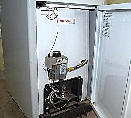
In the basements of private homes often have gyms. In this basement use case, full air exchange is especially important
Simultaneously with the removal of air in the process of air exchange, the moisture released into it by various moisture-containing objects (including people) is removed. Formula for calculating air exchange taking into account the release of moisture:
L = D / ((dat-dP) • p)
Wherein:
- D is the amount of moisture released during air exchange, g / h;
- dat - moisture content in the removed air, g water / kg air;
- dP - moisture content in the supply air, g water / kg air;
- p is the air density (at t 20aboutC is 1.205 kg / m3).
Air exchange, including the release of moisture, is calculated for objects of high humidity (for example, pools). Also, moisture release is taken into account for basements visited by people for the purpose of physical exercise (for example, a gym).
Stably high humidity significantly complicates the work of forced ventilation of the basement. You will need to supplement the ventilation with filters to collect condensed moisture.
Calculation of duct parameters
Having data on the air volume of ventilation, we proceed to determine the characteristics of the ducts. One more parameter is needed - the speed of pumping air through the ventilation duct.
The faster the air stream is driven, the less volumetric air ducts can be used. But system noise and network impedance will also increase. It is optimal to pump air at a speed of 3-4 m / s or less.

Knowing the calculated cross-section of the ducts, you can select their actual cross-section and shape according to this table. And also find out the air flow at certain feed rates
If the basement interior allows you to use round ducts - it is more profitable to use them. In addition, a network of ventilation ducts from round ducts is easier to assemble, because they are flexible.
Here is a formula that allows you to calculate the area of the duct by its section:
Ssv= L • 2,778 / V
Wherein:
- Ssv - estimated cross-sectional area of the ventilation channel (duct), cm2;
- L - air flow when pumping through the duct, m3/ h;
- V is the speed with which air moves in the duct, m / s;
- 2,778 - the value of the coefficient that allows you to agree on heterogeneous parameters in the composition of the formula (centimeters and meters, seconds and hours).
The cross-sectional area of the ventilation duct is more convenient to calculate in cm2. In other units, this parameter of the ventilation system is difficult to perceive.

For each element of the ventilation system, it is better to supply air flow at a certain speed. Otherwise, the resistance in the ventilation system will increase.
However, the determination of the calculated cross-sectional area of the ventilation duct will not allow you to correctly select the cross-section of the ducts, since it does not take into account their shape.
The required duct area can be calculated from its cross section by the following formulas:
For round ducts:
S = 3.14 • D2/400
For rectangular ducts:
S = A • B / 100
In these formulas:
- S - actual cross-sectional area of the ventilation duct, cm2;
- D is the diameter of the rounded duct, mm;
- 3.14 - the value of the number π (pi);
- A and B - height and width of a rectangular duct, mm.
If there is only one airway channel, then the actual cross-sectional area is calculated only for it. If branches are made from the main highway, then this parameter is calculated separately for each “branch”.
Image Gallery
Photo from
Galvanized Steel Ducts
Accessories for assembling the ventilation system
Fixation of ventilation pipes
Exhaust pipe inlet fan
Calculation of the resistance of the ventilation network
The higher the speed of air movement in the ventilation duct, the higher the resistance to movement of air masses in the ventilation complex. This unpleasant phenomenon is called "pressure loss".

If the cross section of the ventilation ducts is gradually increased, then it will be possible to achieve a stable air velocity along its entire length. In this case, the resistance to air movement will not increase
The ventilation unit must develop air pressure to cope with the resistance of the air distribution network. This is the only way to achieve the required air flow in the ventilation system.
The speed of air moving along the ventilation ducts is determined by the formula:
V = L / (3600 • S)
Wherein:
- V is the estimated speed of pumping air masses, m3/ h;
- S is the cross-sectional area of the duct, m2;
- L - required air flow, m3/ h
The choice of the optimal fan model for the ventilation system should be made by comparing two parameters - the static pressure developed by the ventilation unit and the calculated pressure loss in the system.

By positioning the ventilation unit in the center of a branched duct system, it will be possible to stabilize the air supply rate over its entire length
Pressure losses in an extended ventilation complex of complex architecture are determined by summing up the resistance to air movement in its curved sections and stacked elements:
- in the check valve;
- in silencers;
- in diffusers;
- in fine filters;
- in other equipment.
There is no need to independently calculate the pressure loss in each such “obstacle”. It is enough to use pressure loss graphs as applied to air flow, offered by manufacturers of ventilation ducts and related equipment.
However, when calculating the ventilation complex of a simplified design (without typesetting), it is permissible to use typical values of pressure loss. For example, in basements with an area of 50-150 m2 losses on the resistance of the ducts will be about 70-100 Pa.
Exhaust fan selection
To determine the choice of a ventilation installation, you need to know the required performance of the ventilation complex and the resistance of the ducts. For forced ventilation of the cellar, one fan is enough, built into the exhaust duct.
The supply air duct, as a rule, does not need a ventilation installation. A fairly small pressure difference between the points of air supply and its intake, provided by the operation of the exhaust fan.

Knowing the calculated (necessary) pressure in the duct system, you can determine whether this model of the ventilation unit is suitable for a full air supply of the premises. It is enough to find the position by pressure, draw a line to the graph, then down
A fan model is needed, whose performance is slightly (7-12%) higher than the calculated one.
You can check the suitability of the ventilation unit by plotting the performance against pressure loss.

Using the data on the estimated air flow, it is possible to establish the pressure loss in the bent sections of the ducts
If you have to choose between a deliberately more powerful and too weak ventilation installation - the priority remains with the powerful model. However, you will need to somehow lower its performance.
Optimization of a too powerful exhaust fan is achieved in the following ways:
- Install balancing throttle valve before ventilation installation.that allow to "strangle" her.Air consumption with a partial overlap of the exhaust duct will decrease, but the fan will have to work with increased load.
- Turn on the ventilation unit to work in small and medium speed modes. This is possible if the unit supports 5-8 speed control or smooth acceleration. But there are no support for multi-speed operating modes in low-cost models of fans, they have a maximum of 3 speed adjustment levels. And for the correct performance tuning, three speeds are not enough.
- Minimize maximum exhaust system performance. This is feasible if the automation of the fan allows its highest rotation speed to be controlled.
Of course, you can not pay attention to excessively high ventilation performance. However, you will have to overpay for electric and thermal energy, since the hood will too actively draw heat from the room.
Basement ventilation duct diagram
The inlet channel is discharged behind the basement facade, arranged with a mesh fence. Its return output, through which air enters, descends to the floor at a distance of half a meter from the last.
In order to minimize the formation of condensate, the supply duct must be insulated from the outside, especially its “street” part.

To find out the pressure loss in a direct duct system, you need to know the air speed and use this graph
The air intake of the hood is located near the ceiling, at the end of the room opposite the point of location of the air inlet. It is pointless to place the openings of the hood and the supply duct on one side of the basement and at the same level.
Since housing construction standards do not allow the use of vertical channels of natural extraction for forced ventilation, air ducts cannot be installed on them.
It happens when it is impossible to arrange the supply and exhaust channels of the intake-exhaust air on different sides of the cellar (there is only one front wall). Then it is necessary to separate the points of air intake and discharge vertically by 3 meters or more.
This video demonstrates the signs of poor ventilation in the basement. The channels of supply and exhaust air exchange in this cellar seem to be there, but the air does not go through them. There are all the problems of the basement - damp, stale air and plentiful condensate on the building envelope:
The video below shows a practical solution for forced extraction of a cellar using a PC cooler and a solar panel. Note the originality of this ventilation project. For a cellar of the "vegetable store" type, such an implementation of air exchange is quite acceptable:
Since a full decrease in humidity in the basement is impossible without thermal insulation of “cold” pipelines, we present a video on applying tubular insulation. Note that for the technical purpose of the basement, the full winding of a thermally insulated pipe with reinforced tape is rational - this is more reliable:
It is quite possible to turn a “homeless” basement into a room of the desired destination. It is only necessary to solve the problem of air exchange in it and eliminate moisture sources. In any case, the basement of the building should not be a wet, moldy place. After all, its walls are the foundation of a building whose destruction is unacceptable.
Do you want to arrange ventilation in the cellar yourself, but are not sure that you are doing everything right? Ask your questions on the topic of the article in the block below. Here you can share the experience of self-arrangement of ventilation in the cellar or basement.